| .github | ||
| .vscode | ||
| css | ||
| glsl | ||
| include | ||
| lib | ||
| src | ||
| .gitignore | ||
| .gitmodules | ||
| CMakeLists.txt | ||
| glad.c | ||
| glHelper.h | ||
| main.cpp | ||
| README.md | ||
Computer Graphics Lab5 - Shader Pipeline
Deadline: Dec. 13 2024, 22:00
Building with CMake
This project depends on Eigen and GLFW, which are added as submodules in the lib/ folder. After cloning the repository, you need to cd into it and run:
git submodule update --init --recursive
OpenGL is already setup by default on most systems. For example, Windows includes the opengl32.dll library by default in C:/Windows/System32. Drivers for OpenGL are automatically included in most graphics drivers.
Linux: if this was not already installed, run:
sudo apt install libgl1-mesa-dev
sudo apt install freeglut3-dev
Background
Review chapters 6, 7 and sections 8.1–8.2 of Fundamentals of Computer Graphics (4th Edition). Read Sections 11.4–11.5 and Chapter 17 of Fundamentals of Computer Graphics (4th Edition)
In this assignment, we will use the “real-time rendering” shader pipeline of OpenGL. In this assignment, you will build on this workflow to procedurally render a planet. You will be combining knowledge from all the previous assignments: ray tracing, normals, mesh subdivision and perlin noise.

The building blocks of an OpenGL application
1. Shaders written in GLSL
Just like OpenCL had the .cl file with a specific C-style language, OpenGL has the OpenGL shading language (glsl). The extensions are commonly .glsl, .vs, .fs, .tcs The programs in these files are called shaders.
In many ways, glsl code looks like C++ code. However, there are many builtin linear algebra types (e.g., vec3 is a 3D-vector type) and geometric functions (e.g., dot(a,b) computes the dot product between vectors a and b. Since vectors are often used to represent spatial coordinates or colors. We can index the coordinates of a vector (vec3 a) using a.r, a.g, a.b or a.x, a.y, a.z. When working with perspective projection it’s often useful to employ 4D homogeneous coordinates vectors: vec4 in glsl. Glsl has many builtin ways to work with differently sized vectors and matrices. For example, if we have vec4 h then we can write vec3 p = h.xyz; to grab the first three coordinates. Similarly, we could write: vec4 h = vec4(p,1.0) to convert a 3D Cartesian point to a 4D homogeneous point.
Fortunately, there are many online resources and googling a glsl-related question often returns helpful answers.
2. On the CPU side
The shaders you write in this assignment will run on the GPU. Let’s briefly describe what’s happening on the CPU side.
A pseudo-code version of main.cpp might look like:
main()
  initialize window
  copy mesh vertex positions V and face indices F to GPU
  while window is open
    if shaders have not been compiled or files have changed
      compile shaders and send to GPU
    send "uniform" data to GPU
    set all pixels to background color
    tell GPU to draw mesh
    sleep a few milliseconds
3. Window
Creating a window is clearly something that will depend on the operating system (e.g., Mac OS X, Linux, Windows). This assignment, like many small scale graphics programs or games, uses an open source windowing toolkit called glfw. It works on all major operating systems. Once the window is open we have access to its contents as an RGB image. The job of our programs are to fill in all the pixels of this image with colors. The windowing toolkit also handles interactions with the mouse and keyboard as well as window resizing.
OpenGL shaders
Shaders are compiled at runtime. Compilation errors (usually syntax errors) will be output from the main program and the window will turn black (background color).
In this project, you will also be using 4 types of shaders. Each time glDrawElements() is called on the CPU, the shaders are executed in the following order:
- vertex shader
- tessellation control shader
- tessellation evaluation shader
- fragment shader
Below is a simplified example of a vertex shader, which is called once per vertex. In this project, the 3D position pos_vs_in of each vertex is passed to OpenGL in GlHelper::createVAO(). This is indicated through the keyword in. This data is considered an “attribute” of each vertex. Constants (or uniforms) like project have the same value over all shaders. Uniform data is usually changed once per draw frame, or per "object". Variables that need to be passed to the next shader are indicated by out. The goal of the vertex shader is to write the screen space position of the vertex to gl_Position.
#version 410 core      // alway necessary as first line

uniform mat4 project;  // perspective projection matrix

in vec3 pos_vs_in;     // 3D position of mesh vertex

out vec3 pos_fs_in;    // passed to next shader

void main() {
    pos_fs_in = pos_vs_in;
    gl_Position = project * vec4(pos_vs_in, 1);
}
After rasterization, the fragment shader is called for each pixel, to determine the value (color) of that pixel. For example:
#version 410 core     // alway necessary as first line

in vec3 pos_fs_in;    // passed from previous shader

out vec3 color;       // OpenGL will write this to the screen

void main() {
    color = 0.5+0.5*pos_fs_in;
}
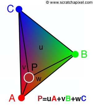
Say that we draw a triangle to the screen. The vertex shader is called 3 times, so pos_fs_in has 3 different values (A, B, C in the image below). Note however that after the triangle is rasterized, it can cover many pixels on the screen, hundreds to thousands. So what is the value of pos_fs_in (P) in the fragment shader (which is called once per pixel)? Answer: the value of pos_fs_in (P) for a pixel is linearly interpolated between the 3 pos_fs_in values (A,B,C) of the vertices of the triangle. The weights for the linear interpolation are the barycentric coordinates (u,v,w) of the pixel in the triangle. OpenGL takes care of this interpolation for you.
Tessellation control shader
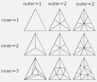
The tessellation control shader determines how to subdivide each input “patch” (i.e., triangle). Unlike the subdivision we saw with subdivision surfaces, the subdivision is determined independently for each triangle and not called recursively. The exact pattern of the resulting triangulation is left largely to implementation. As the shader programmer, you have control over:
- the number of new edges each input should split into (
gl_TessLevelOuter[1] = 5means the edge across from vertex1(i.e., the edge between vertices0and2) should be split into 5 edges); and - the number of edges to place toward the center of the patch (
gl_TessLevelInner[0] = 5would be a good choice ifgl_TessLevelOuter[...] = 5and a regular tessellation was desired).
To get a better understanding of tessellation, please read this Stackoverflow post:
Unlike the vertex or fragment shader, the tessellation control shader has access to attribute information at all of the vertices of a triangle. The main responsibility of this shader is setting the gl_TessLevelOuter and gl_TessLevelInner variables.
Tesselation evaluation shader
The tessellation evaluation shader takes the result of the tessellation that the tessellation control shader has specified. This shader is called once for every vertex output during tessellation (including original corners). It has access to the attribute information of the original corners (e.g., in our code in vec3 pos_es_in[]) and a special variable gl_TessCoord containing the barycentric coordinates of the current vertex. Using this information, it is possible to interpolate information stored at the original corners onto the current vertex: for example, the 3D position. Like the vertex and tessellation control shader, this shader can change the 3D position of a vertex. This is the last opportunity to do that, since the fragment shader cannot.
Bump mapping
Intuition
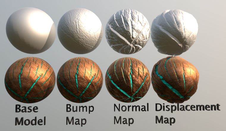
Bump mapping a technique to make a lit surface look like it has a lot of surface detail. However, unlike displacement mapping, the vertices of the mesh are not actually modified/displaced. As you can see on the image below, the geometry of the base model is unaltered by the bump map, while the displacement map moves the vertices.
Bump mapping happens in the fragment shader. Conceptually, a bump map assigns an imaginary height offset ("bump") `h(p)` to each point (pixel) `p` on the mesh, along the surface normal `n̂(p)` at that point. If you recalculate the normal vector for that pixel, now keeping in mind the bumpy surface, you get a new normal vector `ñ`. If you use the new normal during the lighting calculation, e.g. Blinn Phong shading, you will get the bumpy surface look. So compared to normal mapping, where the new normal vector is already known for each pixel, in bump mapping the new vector needs to be calculated.
Calculating `ñ`
In a mathematical sense, a normal map is non-sense. A point on a surface has a specific normal completely determined by its local geometry. The normal is the direction that goes in the most outward direction from the surface. That is, the normal is perpendicular to the surface. Since a surface is two dimensional, the directions that stay on the surface are spanned by a two dimensional tangent plane.
Normal mapping is useful in computer graphics because we can drape the appearance of a complex surface on top a low resolution and simple one. To create a consistent and believable looking normal map, we can first generate a plausible bump map. Each point `p∈ℝ³` on the surface is moved to a new position `p̃∈ℝ³` :
p̃(p):=p+h(p) \hat{n}(p)where $h: ℝ³ → ℝ$ is the bump height amount function (could be negative) and $n̂(p): ℝ³ → ℝ³$ is the mathematically correct normal at `p`.
If our bump height $h$ is a smooth function over the surface, we can compute the perceived normal vector $ñ$ by taking a small finite difference of the 3D position:
ñ=\frac{∂p}{∂T} × \frac{∂p}{∂B} ≈ (\frac{p̃(p+εT)−p̃(p)}{ε})×(\frac{p̃(p+εB)−p̃(p)}{ε})where $T,B ∈ ℝ³$ are orthogonal tangent and bi-tangent vectors in the tangent plane at $p$ and $ε$ is a small number (e.g., 0.0001). By abuse of notation, we’ll make sure that this approximate perceived normal is unit length by dividing by its length:
ñ←\frac{ñ}{∥ñ∥}Before you start implementing
How come I can’t use #include in the GLSL shader files?
Our glsl shader programs are not compiled beforehand from files. Instead the CPU-side program must read the file contents into memory as strings and provide the raw strings to the shader compiler. Unfortunately, this means there is no #include preprocessor directive and sharing code across different shaders is a burden. In this assignment, it is hard coded which glsl files are read in and compiled, take a look at path_glsl_files.h. The used glsl files will also always be printed to the command line.
How to debug a shader program?
Debugging shader programs must be done visually. Since we only see the result of all computation, we can use the shader pipeline’s ability to set screen colors to debug all computation simultaneously. For example, when debugging the fragment shader we can check all values at once by setting the pixel color to a value we expect (or don’t expect) depending on the computation. A few useful commands come in handy:
color = 0.5 + 0.5 * n; // will set the color based on the normal n.
                       // green = points up, blue = points left, red = points right
color = vec3(0.5,0.5,0) + vec3(0.5,0.5,0) * view_pos_fs_in.xyz; // will set the color based on the view position.
color = -view_pos_fs_in.z /15 *vec3(1,1,1); // will set the color based on the distance to the camera in the z-direction.

color = vec3(float(is_moon),1,0); // will set the color to yellow or green based on a boolean value (in this case is_moon).
Homogeneous coordinates, vec4 vs. vec3
In computer graphics applications, 3D points are often stored as a vec4 point = vec4(x,y,z,w) = vec4(x,y,z,1) with w = 1. For our purposes, this makes it easy to transform the position of a vertex through multiplication with 4x4 matrices (mat4 ). Notably a translation matrix uses the fourth column to translate the point. Most projection matrices also use the fourth column and row.
However, some vectors purely represent a direction, for example a normal vector. For such vectors, w needs to be zero! For example, multiplying a normal vector with a translation mat4 should not alter the normal vector, since the direction should stay the same. This is achieved by setting w = 0, so vec4 normal = vec4(x,y,z,0).
Tasks
You will be implementing the glsl files in the src/ folder. This assignment works best if you implement the following tasks in order.
Note: the
glsl/folder contains helper methods, for examplePI.glsl. The glsl files insrc/that you will implement will contain "Hints" as to which existing methods you can (and should) use.
Note: we implemented the project so that you can alter the glsl files while the
shaderpipelineexecutable is running, and the program will automatically detect the changed code, recompile the shader and use it to render the image in the window.
Whitelist: mix, normalize, length, clamp, sin, cos, abs, pow, ...
Blacklist: noise1, noise2, noise3, noise4
The correct results for each task are included in this readme file; their original gifs can be found in the css/ folder (unordered).
Task 0: check if OpenGL works. Run:
./shaderpipeline 0         (Unix)
shaderpipeline.exe 0       (Windows)
You should see a window pop up that looks like the image below. If you see a completely black window, something went wrong. Feel free to contact us with info about your setup.
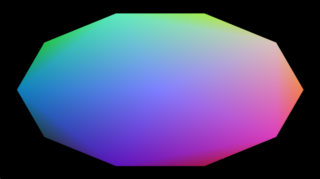
Task 1: basic model, view, projection. What you see above is actually two icosahedrons being rendered to the screen, one is supposed to be a planet and the other a moon. You need to implement the transformation to project the vertices (in object space) to the screen (in screen space):
-
1_identity.glsl -
1_uniform_scale.glsl -
1_translate.glsl -
1_rotate_about_y.glsl -
1_model.glsl -
1_model_view_projection.vs: the vertex shader, which uses the methods above to project a vertex fromobject -> world -> eye -> screenspace. -
1_blue_and_gray.fs: the fragment shader, which gives each pixel a color.
These should be implemented so that when you run ./shaderpipeline 1, you get an animation of a gray moon orbiting a blue planet:
If you press L this should switch to a wireframe rendering:

Task 2: subdivide the mesh. Our icosahedrons are rather low poly. To subdivide each face, implement:
2_tessellate_5.tcs
Running ./shaderpipeline 2 and pressing L should now show that the planet and moon are subdivided, i.e. have more triangles.
Task 3: make the mesh round. Make the mesh vertices sit on a sphere by implementing:
3_snap_to_sphere.tes: the tessellation evaluation shader, executed right after2_tessellate_5.tcs.
Running ./shaderpipeline 3 should look like:
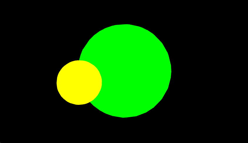
Task 4: light. Our scenario is looking quite flat, let's add a point light and implement Blinn Phong shading to show the roundness of the planet and moon:
-
4_blinn_phong.glsl -
4_lit.fs
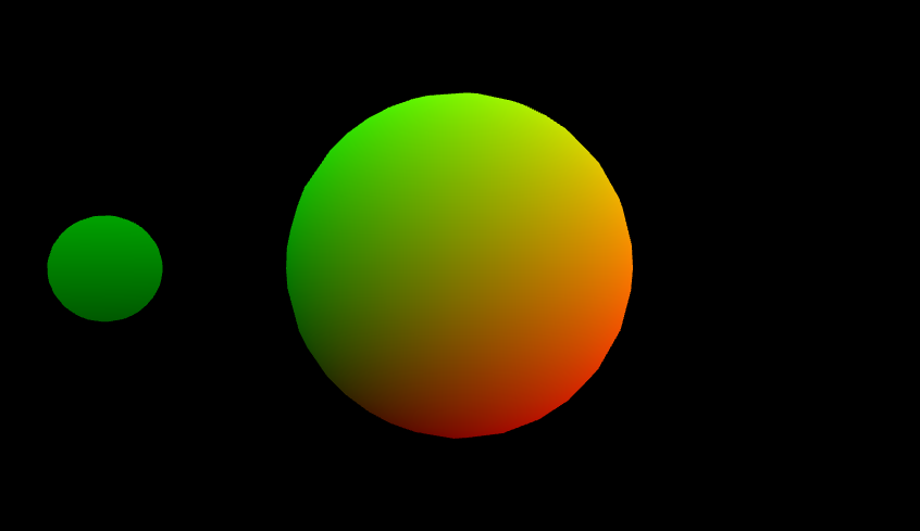
Running ./shaderpipeline 4 should look like:
Task 5: procedural color. As promised, perlin noise (along with random_direction and smooth_step) returns, in this case to build the color texture of the planet and moon. Important: the input is now a vec3, so implement 3D perlin noise instead of 2D! Important: do not normalize the perlin noise, let it keep its inherint (negative) minimum and (positive) maximum value.
-
5_random_direction.glsl -
5_smooth_step.glsl: use the improved version, discussed in the epilogue of the previous assignment. -
5_perlin_noise.glsl -
5_procedural_color.glsl
Running ./shaderpipeline 5 should look like (feel free to zoom in using the scroll wheel):
Task 6: procedural bump. Your perlin noise method can also be used to vary the height of the planet's and moon's surface:
-
6_bump_position.glsl -
6_tangent.glsl -
6_bump.fs: use what you learned about bump mapping earlier in this document to recalculate the normals to create a bumpy looking surface.
Running ./shaderpipeline 6 should look like:
Task 7: get creative. Play around in 7_planet.fs to build your own visualization, using everything you've implemented so far. You can visualize it by running ./shaderpipeline 7. Here is an example, but fun variations on this are also welcome:

Epilogue
This section is dedicated to the enthousiasts that want to delve deeper into OpenGL as a hobby to create their own applications. The best resource to quickly learn OpenGL is learnopengl.com. You will draw and light your own meshes in no time, while mastering the fundamentals of computer graphics.
This marks the end of the practicals. Thank you for following the Computer Graphics course. We hope that you now have a better understanding of how the graphics on your screen are created and are inspired to develop your own visualizations.
Good luck on your journey!
- Julie and Bert